Brailliant
Brailliant
A modular refreshable Braille device powered by multimodal LLMs
Brailliant is an integrated solution for accessible Braille translation technology. The world's first scene-to-braille conversion technology is powered by multimodal LLMs and custom-designed electronics. This device allows for live-time conversion of any text into Braille, increasing accessibility to books and printed material.
Contents
WARNING: The project video and slide (poster) are out of date and provide incorrect information about licensing. The current EULA is here. By installing, accessing, or using the Product, you acknowledge that you have read this Agreement, understand it, and agree to be bound by its terms and conditions.
Overview
I created a 3×2 solenoid array that can display Braille characters by pushing solenoids up and down to create dots. This solenoid array is connected to a Raspberry Pi, which in turn is connected to an ESP32CAM. The camera takes a picture of a page of text, then performs OCR (optical character recognition) to extract a string of text from the image. That string of text is converted to Braille, which is displayed on the solenoid array by flashing each character for 1 second at a time. This device essentially allows for live-time conversion of any text into Braille, which increases accessibility to books and printed material.
Brainstorming Process
Initial Thoughts
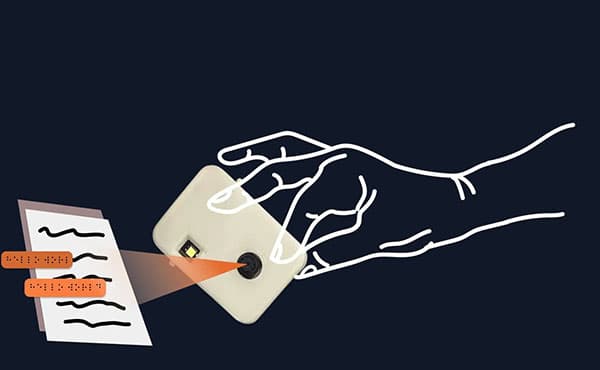
My idea was to design a text-to-Braille converter, which a blind person could use by moving the device over a page of text to convert it into Braille. The Braille translation would be represented via a series of up/down pins that the user could interpret.
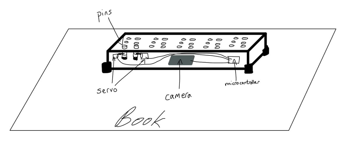
The device was to be a rectangular box that would use an internal camera to interpret and OCR text, which could then be translated into Braille and displayed via a series of servo motors pushing up metal rods on the top of the box. The pins would be in groups of six, each group representing a single Braille character.
After talking with another engineer who had attempted a similar mechanism for another project, I learned that fitting many servos into a small space was infeasible and redesigned my approach.
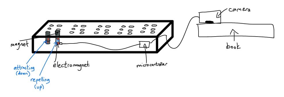
After the initial feedback, I decided to use electromagnets for the pins instead of servos. Each pin would be a small magnetic rod sitting on top of an electromagnet that could be powered on and off via a microcontroller. When off, the pin would rest on the electromagnet, flush against the top of the board (down position). When on, the electromagnet would emit a repelling charge to push the pin upward (up position). I also decided to move the camera out of the box for simpler wiring and easier operation. This way, the user would only need to move a small camera container across the page, rather than the entire device.
Significant Changes
As the project evolved, I made several key modifications:
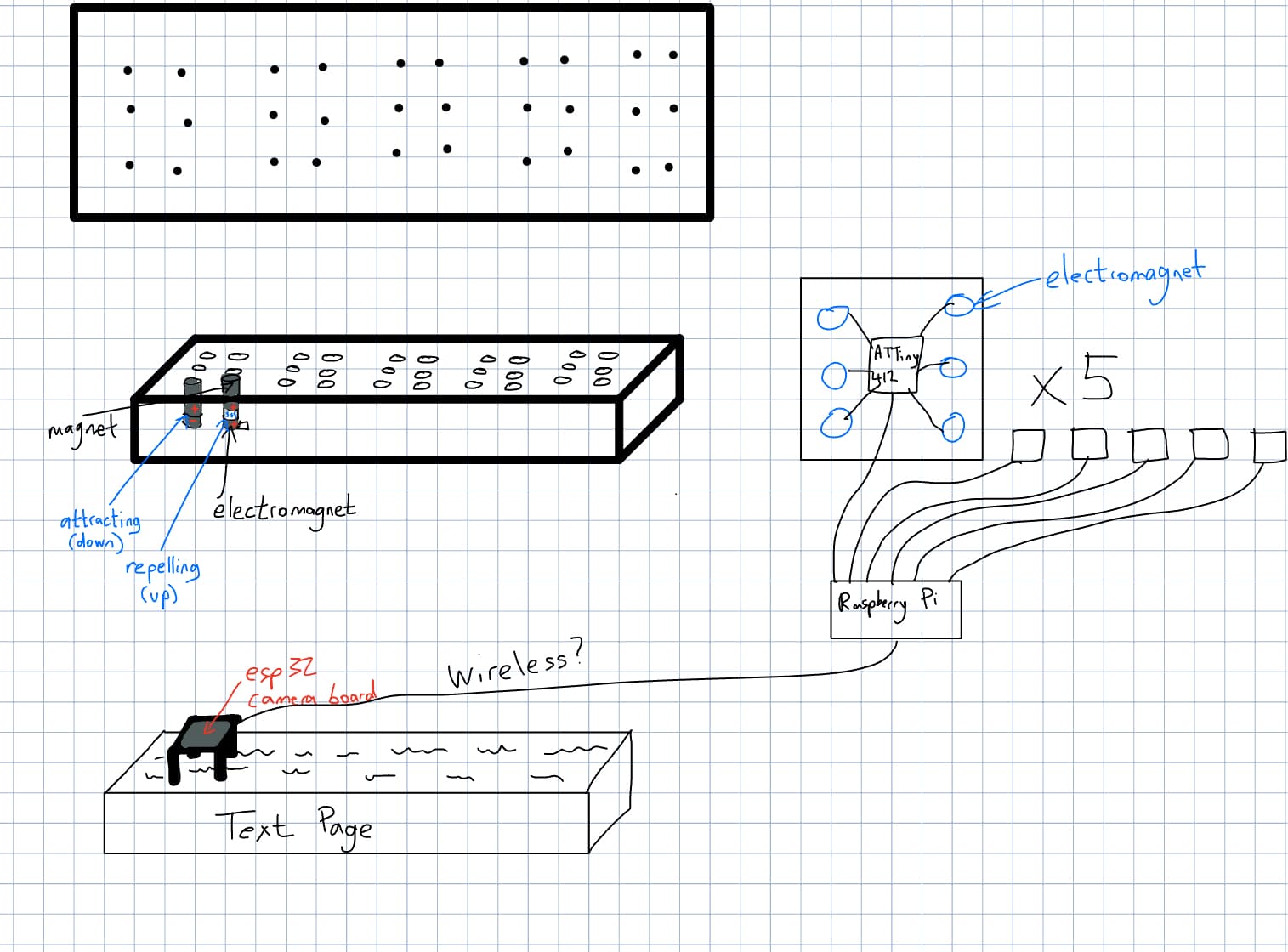
- Using a Raspberry Pi as a central controller connected to ATTiny412 chips, each controlling 6 electromagnets for one Braille character
- Creating an elevated case for the ESP32 camera for better image angle and lighting
- Implementing wireless transmission from the ESP32 camera to the Raspberry Pi
- Scaling down from 30 solenoids (five 3×2 arrays) to just 6 solenoids (one 3×2 array) for feasibility
Feasibility Considerations
After researching power requirements and mechanical constraints, I realized that having 30 solenoids would be unfeasible. Instead, I scaled the project down to just 6 solenoids in a single Braille cell, flashing each character for 1 second.
This change significantly reduced the power budget concerns and ensured a working prototype could be completed on schedule. The single Braille cell still accomplished the core mission of displaying Braille for a reader.
Bill of Materials
Note: Some components were sourced from the lab which reduced overall costs. Prices may vary depending on supplier and quantity ordered.
Hardware Implementation
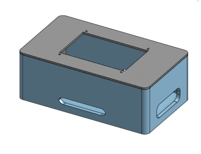
Braille Box CAD
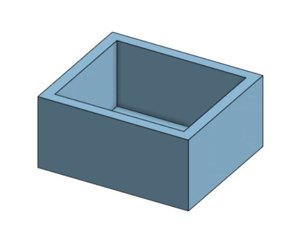
I designed the Braille display enclosure in Fusion360, beginning with a basic shape and refining it through an iterative process.
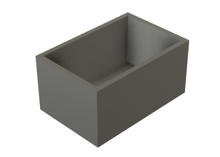
Initial hollowed box shell
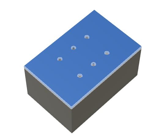
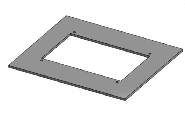
Cover with holes for solenoids
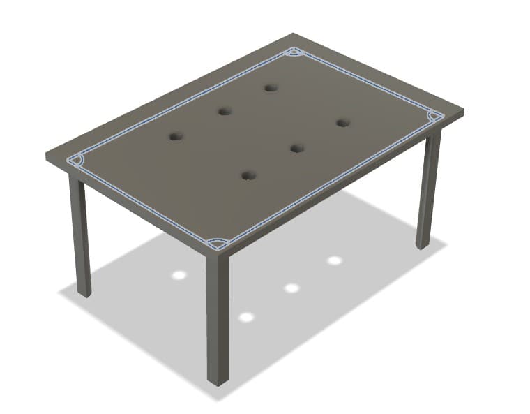
Press-fit lid design
The improved box design includes several key features:
- A 3×2 solenoid array layout (reduced from the initial design)
- Internal beams to support and properly position the solenoids
- Battery pack holders built into the case
- A press-fit cover with precisely positioned holes
- Wire routing channels to maintain a clean appearance
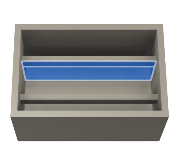
Internal support beams for solenoids
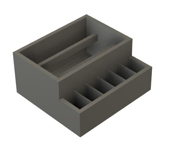
Battery compartment dividers
Final Braille box design with fillets
Raspberry Pi Box CAD
Initial Pi box shell
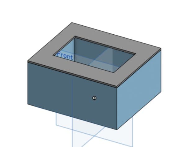
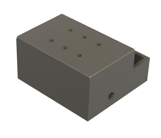
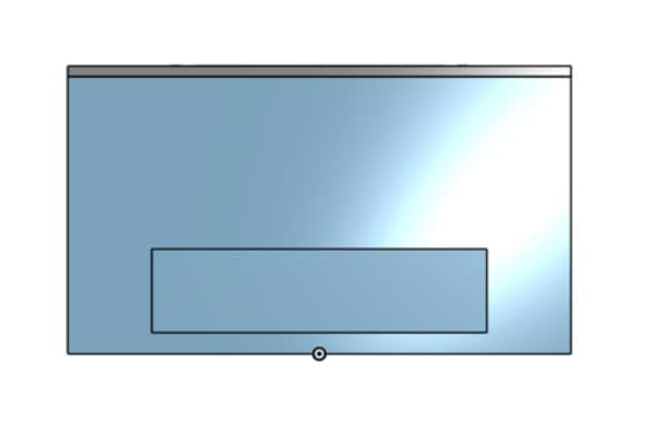
Lid with screen opening
Added screw holes for screen mounting
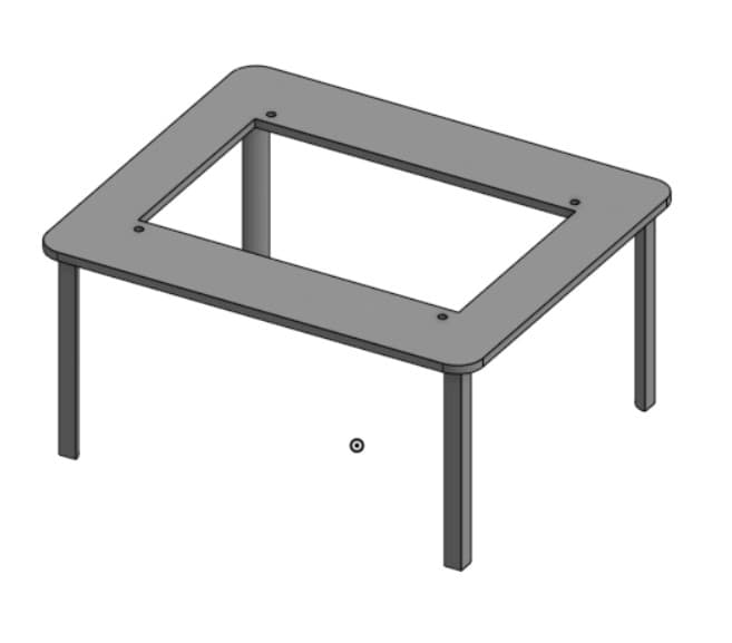
Press-fit legs on the lid
Holes for cable management
After the initial print, I discovered issues with cable routing - some cables had rigid "necks" that didn't fit well in the enclosure. I made adjustments to the box length to accommodate these cables and refined the cable holes to improve the aesthetic.
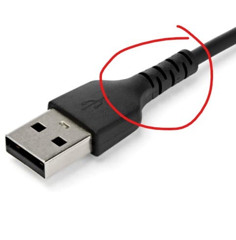
Cable fitting issue discovered
Size adjustments to accommodate cables
Electronics & PCB Design
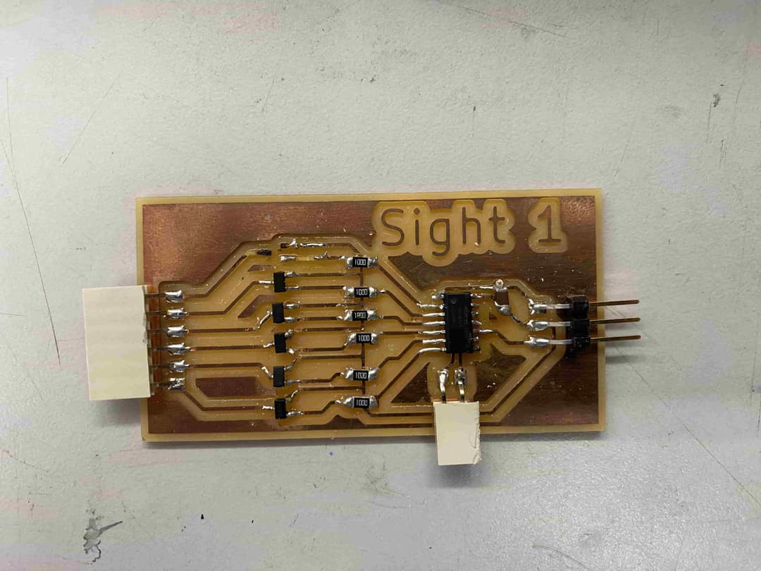
The electronic design posed significant challenges, particularly with transistors and power handling. I went through multiple failed iterations before finding a working solution.
The main issues were:
- Transistors not able to handle the power required by the solenoids
- Inconsistent transistor pinouts causing confusion
- Thermal issues causing components to melt off the board
After several attempts, I ultimately used MOSFET drive modules which could properly handle the current requirements of the solenoids.
First PCB attempt - transistor failure
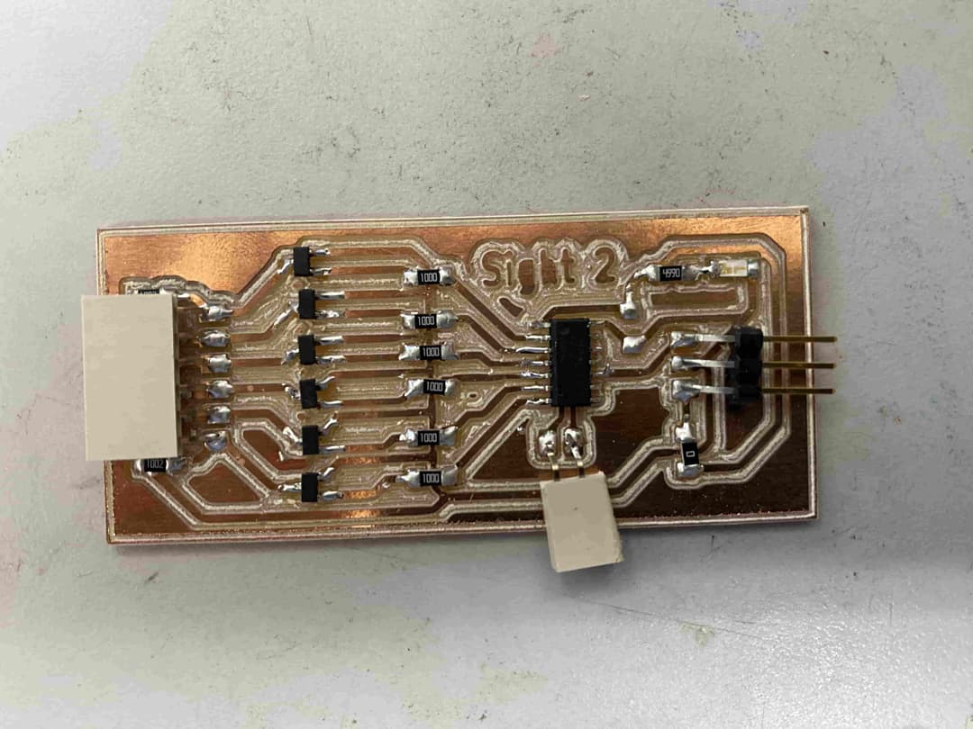
Second PCB with pull-down resistors
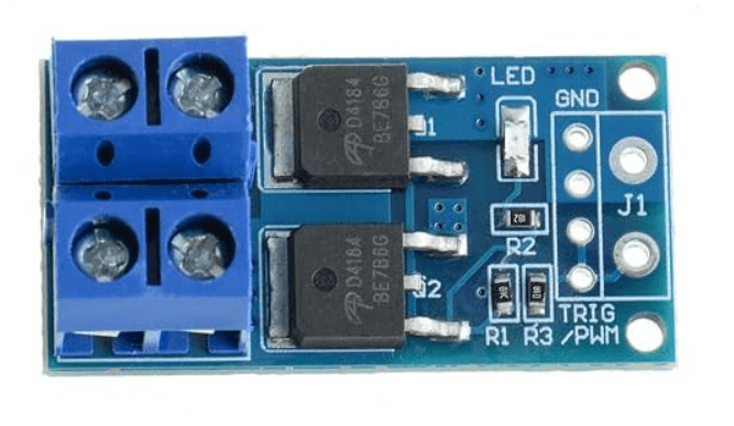
Final solution: MOSFET drive module
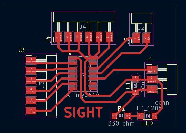
My final control board design includes:
- ATTiny1614 microcontroller
- Headers for power, ground, and data
- Power indicator LED
- Capacitor for stable power
- Serial communication pins for Raspberry Pi connection
- 6 GPIO pins for controlling individual solenoids
- 6 ground connections for the MOSFET modules
By moving the MOSFETs external to the main board, I was able to create a much more reliable system that could properly handle the power requirements of the solenoids.
Software & Programming
ESP32CAM Wireless Transmission
The ESP32CAM communicates with the Raspberry Pi using a WebSocket server that enables bidirectional communication. The camera is initialized with specific configuration parameters, including resolution, quality settings, and frame handling.
When a connection is established, the ESP32CAM waits for commands from the Raspberry Pi. When it receives a "capture" command, it takes a photo and sends the image data through the WebSocket connection.
#include "esp_camera.h"
#include "WiFi.h"
#include "WebSocketsServer.h"

#define CAMERA_MODEL_AI_THINKER // Has PSRAM
#include "camera_pins.h"

const char* ssid = "REDACTED";
const char* password = "REDACTED";

WebSocketsServer webSocket = WebSocketsServer(81);

void onWebSocketEvent(uint8_t client_num, WStype_t type, uint8_t *payload, size_t length) {
  switch (type) {
    case WStype_DISCONNECTED:
      Serial.printf("[%u] Disconnected!\n", client_num);
      break;
    case WStype_CONNECTED:
      {
        IPAddress ip = webSocket.remoteIP(client_num);
        Serial.printf("[%u] Connection from ", client_num);
        Serial.println(ip.toString());
      }
      break;
    case WStype_TEXT:
      if (strcmp((char *)payload, "capture") == 0) {
        camera_fb_t *fb = esp_camera_fb_get();
        if (!fb) {
          Serial.println("Camera capture failed");
        } else {
          webSocket.sendBIN(client_num, fb->buf, fb->len);
          esp_camera_fb_return(fb);
        }
      }
      break;
  }
}
I also implemented a custom handler that encodes the camera feed in base64 format, which proved useful for the GPT-4o integration later in the project.
Camera Feed OCR
For text recognition, I experimented with two different approaches:
PyTesseract Approach
import time
import cv2
import urllib.request
import numpy as np
import pytesseract

url = 'http://10.12.28.193/capture'

img_resp = urllib.request.urlopen(url)
imgnp = np.array(bytearray(img_resp.read()), dtype=np.uint8)
frame = cv2.imdecode(imgnp, -1)

text = pytesseract.image_to_string(frame, config='--psm 7')

print("Extracted Text:", text)
time.sleep(1)
Initially, I used PyTesseract for OCR. The script connects to the ESP32CAM's capture endpoint, downloads the current frame, and processes it with Tesseract OCR.
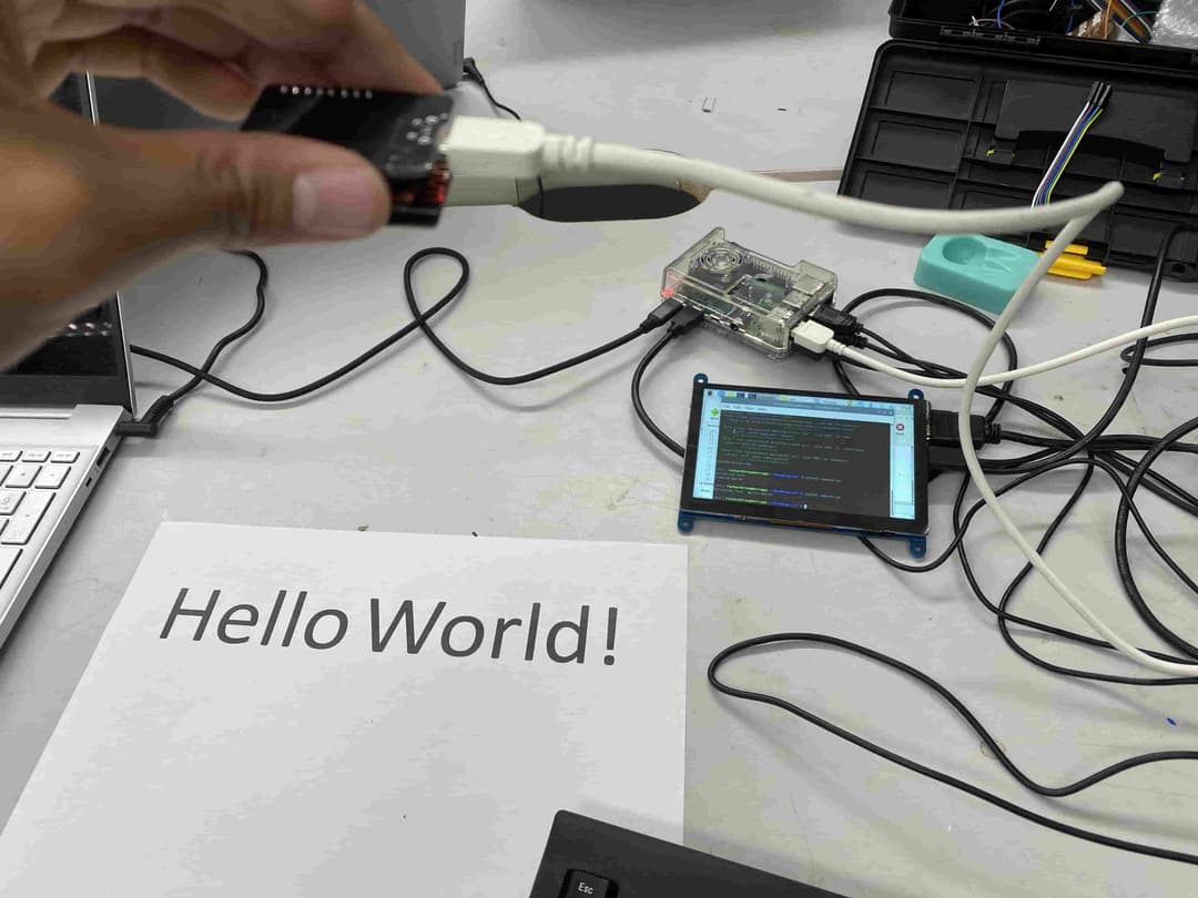
I configured it with PSM 7 (Page Segmentation Mode) to treat the image as a single text line, which worked well for simple text displays like "Hello World!"
Demonstration of Use Case on Macbeth
GPT-4o Multimodal Approach
To improve OCR accuracy, I implemented a second approach using GPT-4o's multimodal capabilities. This approach proved much more accurate, especially for handling varied lighting conditions and fonts.
import requests

# Function to get the base64 encoded image from ESP32CAM
def get_base64_image(url):
    response = requests.get(url)
    return response.text

# URL to the ESP32CAM base64 image endpoint
esp32cam_url = "http://10.12.28.193/base64"

# Getting the base64 string
base64_image = get_base64_image(esp32cam_url)

payload = {
  "model": "gpt-4o",
  "messages": [
    {
      "role": "user",
      "content": [
        {
          "type": "text",
          "text": "You are an image to text OCR engine. Output the text you see in this image, and nothing else."
        },
        {
          "type": "image_url",
          "image_url": {
            "url": f"data:image/jpeg;base64,{base64_image}"
          }
        }
      ]
    }
  ],
  "max_tokens": 300
}

# Extract the recognized text from the response
extracted_text = response.json()['choices'][0]['message']['content']
The final implementation integrated this OCR functionality with serial communication to the ATTiny1614 controller, sending the extracted text for conversion to Braille.
Text to Braille Mapping
The ATTiny1614 controller converts incoming text to Braille patterns and activates the appropriate solenoids to display each character sequentially.
/*
  Solenoid arrangement:
  0 1
  2 3
  4 5
*/

int sols[6] = {0, 1, 2, 3, 9, 8}; // Define the pins connected to the solenoids

// Define the Braille arrays
int a[6] = {0, 1, 1, 1, 1, 1};
int b[6] = {0, 1, 0, 1, 1, 1};
int c[6] = {0, 0, 1, 1, 1, 1};
int d[6] = {0, 0, 1, 0, 1, 1};
int e[6] = {0, 1, 1, 0, 1, 1};
// ... more character definitions ...

// Define a structure to map characters to their Braille arrays
typedef struct {
    char character;
    int *braille_array;
} BrailleMap;

// Create the mapping
BrailleMap braille_dictionary[] = {
    {'a', a}, {'b', b}, {'c', c}, {'d', d}, {'e', e},
    // ... more mappings ...
};

void setup() {
    // Initialize the solenoid pins as output
    for (int i = 0; i < 6; i++) {
        pinMode(sols[i], OUTPUT);
    }
    Serial.begin(9600);
}

void activate_solenoids(int *braille_array) {
    for (int i = 0; i < 6; i++) {
        digitalWrite(sols[i], braille_array[i]);
    }
}

// Function to parse the input string and activate solenoids
void parse_input_string(const char *input) {
    int len = sizeof(braille_dictionary) / sizeof(BrailleMap);
    for (int i = 0; i < strlen(input); i++) {
        for (int j = 0; j < len; j++) {
            if (braille_dictionary[j].character == input[i]) {
                activate_solenoids(braille_dictionary[j].braille_array);
                delay(1000); // Wait for a second before next character
                break;
            }
        }
    }
    deactivate_solenoids();
}

void loop() {
  if (Serial.available() > 0) {
    // Read the incoming string from Raspberry Pi
    String input = Serial.readString();
    // Convert to C-style string and display
    char inputArray[input.length() + 1];
    input.toCharArray(inputArray, input.length() + 1);
    parse_input_string(inputArray);
    delay(5000); // Wait before repeating
  }
}
The controller code maps each character to its corresponding Braille pattern of solenoid activations. When it receives text from the Raspberry Pi via serial communication, it parses the text character by character, displaying each Braille representation for one second before moving to the next.
System Integration
System integration was a critical phase where all the hardware and software components were brought together into a cohesive, functioning system. This involved connecting the Raspberry Pi to both the ATTiny1614 microcontroller and the ESP32CAM, establishing reliable communication protocols, and ensuring that the power management was sufficient for all components.
The integration followed a layered approach:
- Data Layer: ESP32CAM captures images and transmits them to Raspberry Pi
- Processing Layer: Raspberry Pi performs OCR and text-to-Braille conversion
- Output Layer: ATTiny1614 controls solenoids to display Braille patterns
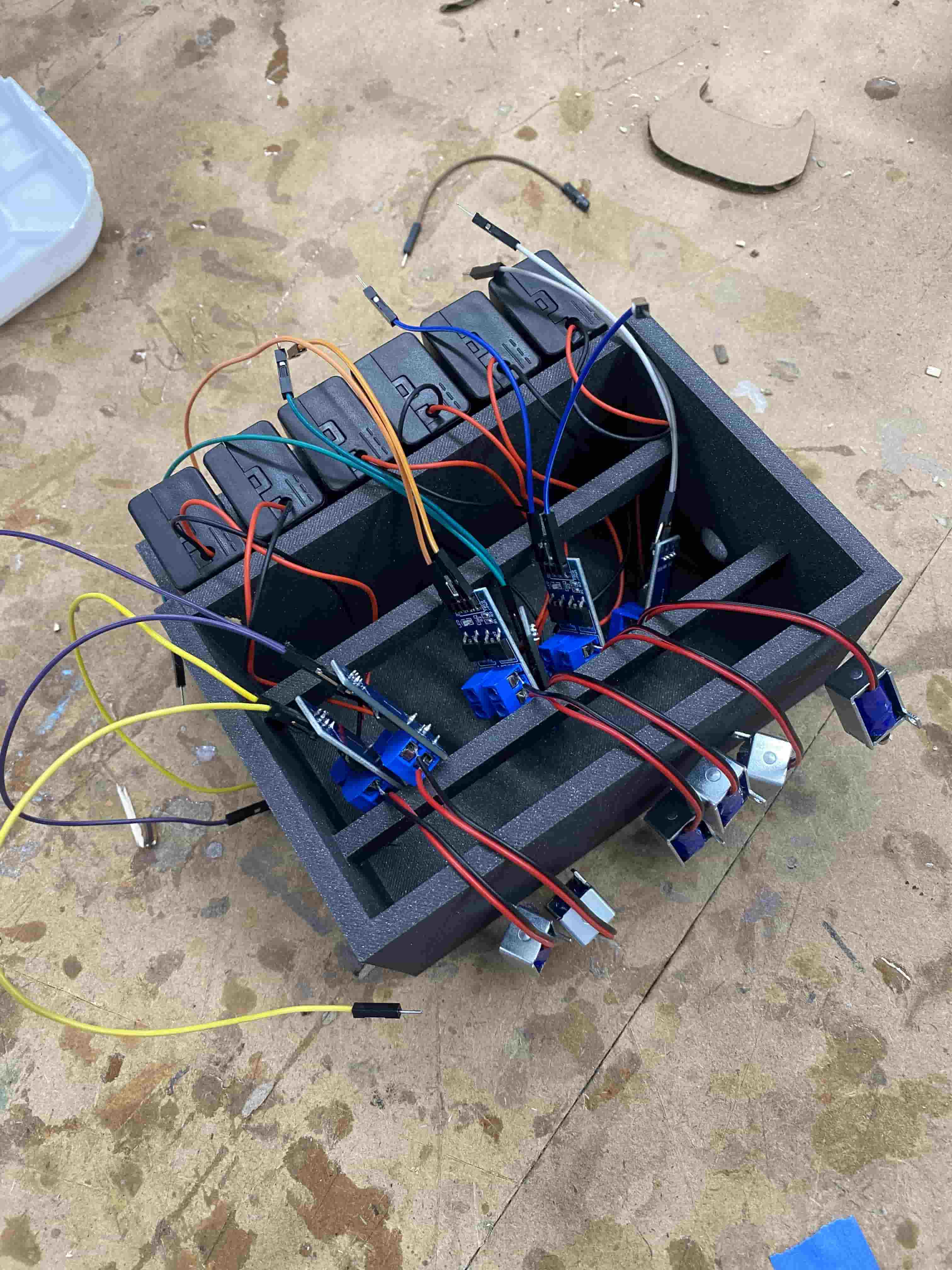
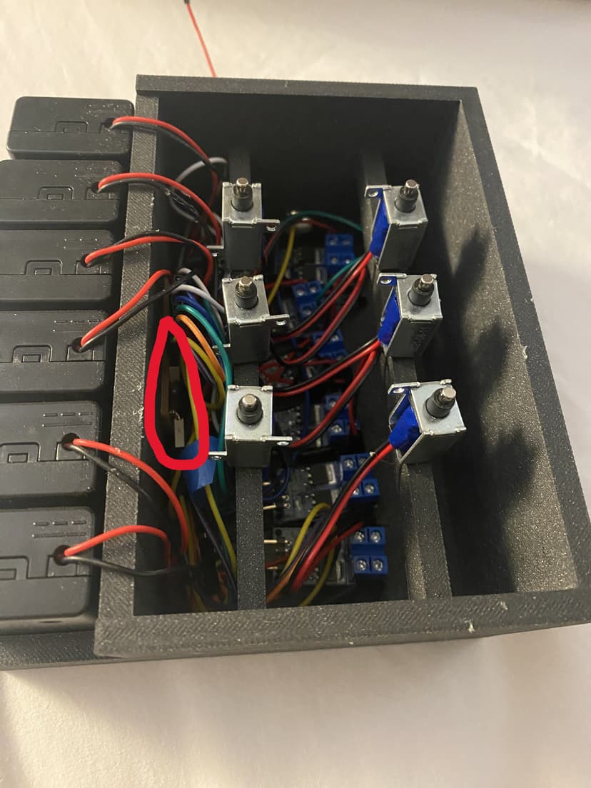
The assembly process began with organizing the components in the Braille box. I secured each MOSFET to a corresponding battery pack and solenoid, using color-coded wiring to maintain organization.
Each solenoid was driven by a dedicated MOSFET module, which handled the current requirements that couldn't be managed directly by the microcontroller GPIO pins.
The wiring was organized so that toggling solenoids 1 through 6 would control each solenoid in sequential order, matching the standard Braille cell arrangement.
Testing all solenoids in sequence during initial integration
For final assembly, I secured all components in place, using Nitto tape to attach the PCB to the side wall and hot glue to secure the MOSFETs and solenoids in their respective positions.
The color-coded wiring scheme made it easier to debug individual components and troubleshoot connections:
- Top-left solenoid: white wires
- Top-right solenoid: dark blue wires
- Mid-left solenoid: green wires
- Mid-right solenoid: orange wires
- Bottom-left solenoid: blue wires
- Bottom-right solenoid: yellow wires
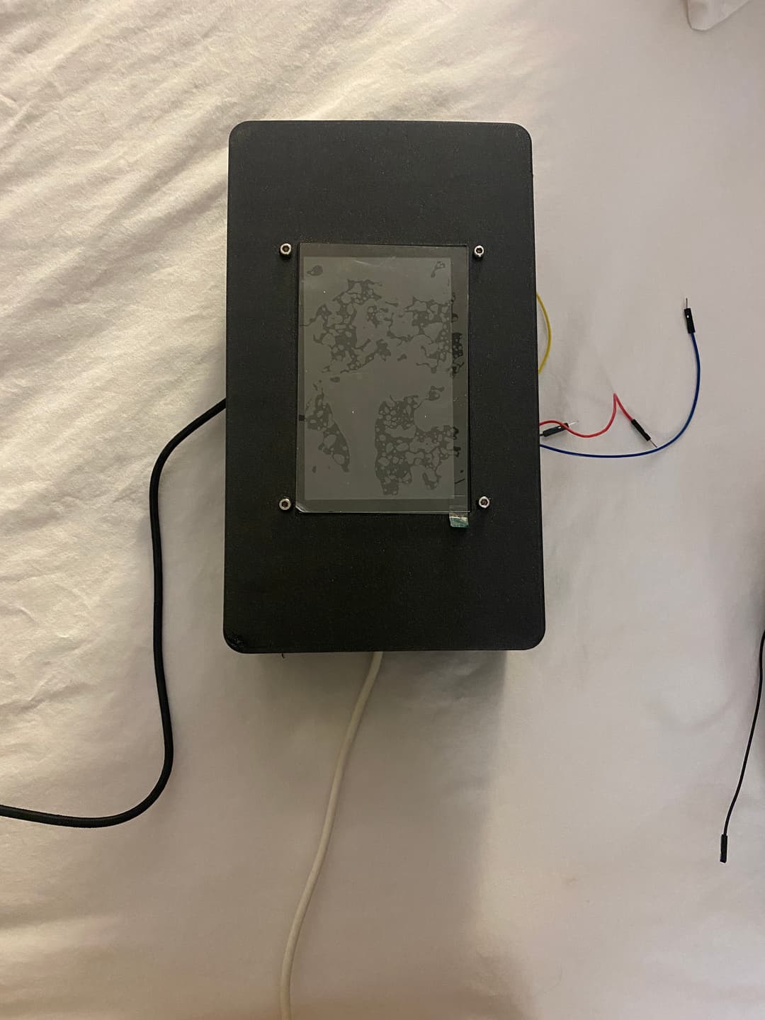
Testing the fully assembled solenoid array
Raspberry Pi Assembly
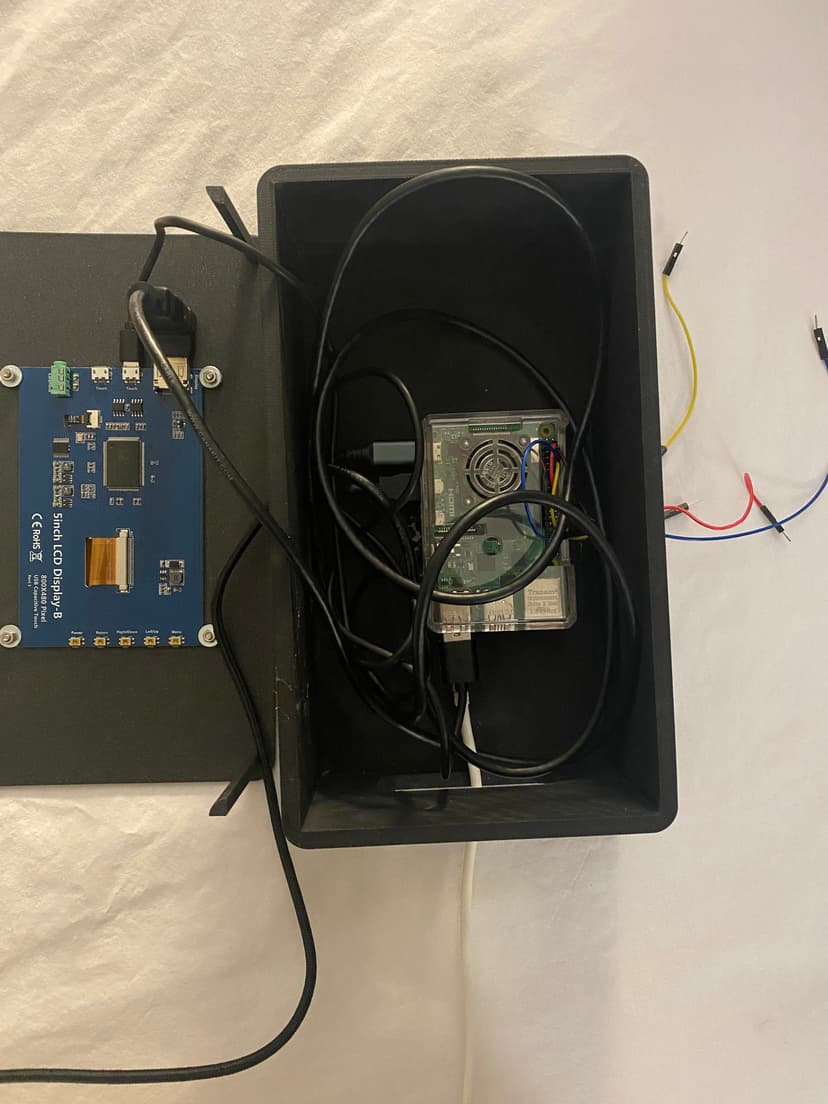
The Raspberry Pi case assembly was relatively straightforward thanks to the purpose-built design with cable routing holes and screen mounting provisions.
I secured the touchscreen to the lid using four M3 screws in the pre-designed mounting holes, and attached the Raspberry Pi to the bottom of the case using hot glue for stability.
The connections included:
- microHDMI connection to the display
- Power cable through the left side hole
- ESP32CAM connection via the bottom hole
- Wires to the Braille box's ATTiny1614 through the right side hole
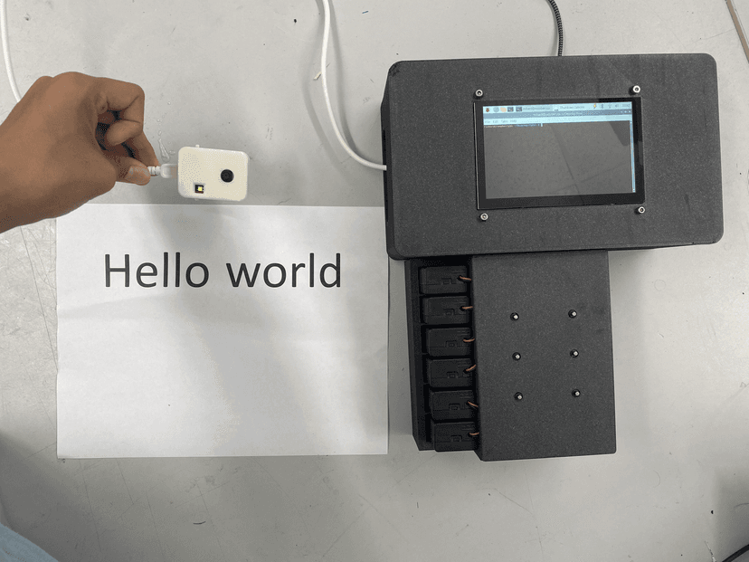
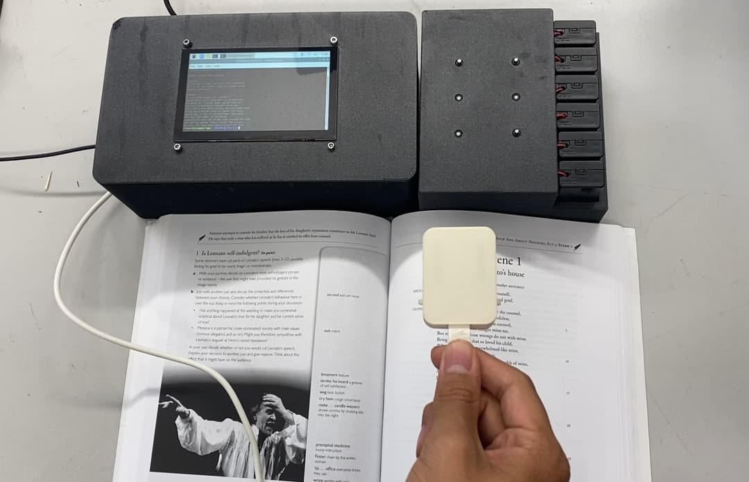
Setup for usage of the final integrated system
Integration Challenges & Solutions
Several challenges emerged during the integration process that required creative solutions:
- Power Management: The solenoids required significant current, which neither the Raspberry Pi nor the ATTiny1614 could directly provide. The solution was to use separate power sources for each solenoid with MOSFET modules as switching interfaces.
- Heat Dissipation: During extended operation, the MOSFETs generated considerable heat. I added small heat sinks and designed ventilation gaps in the Braille box to improve airflow and prevent overheating.
- Communication Timing: Initial tests showed timing issues between the image capture, processing, and Braille output. I implemented a simple handshaking protocol between the Raspberry Pi and ATTiny1614 to ensure proper synchronization.
- Wireless Stability: The ESP32CAM connection occasionally dropped during operation. I improved reliability by implementing connection retry logic and error handling in the WebSocket implementation.
The final integrated system demonstrates how multiple specialized subsystems can work together to create a novel accessibility solution. Each component was designed with clear interfaces, making future upgrades and modifications straightforward.
Final Product & Evaluation
The completed Brailliant device successfully met all the project goals:
- ✓ Accurately extracts text from live image feed
- ✓ Maps text to Braille patterns
- ✓ Displays Braille characters sequentially on the solenoid array
While commercial Braille displays exist, they are often prohibitively expensive. Brailliant demonstrates how modern computer vision and LLMs can create more affordable, accessible solutions for the visually impaired.
Key Lessons Learned
- Some parts of a project will take longer while others will take shorter than expected
- Always double the planned allocation of time due to errors and debugging needs
- Working with lower-level hardware and software is more rewarding and often produces a more solid product
- There are many types of transistors, which can be a pain to sort through
- Modern AI models like GPT-4o can dramatically improve accessibility applications
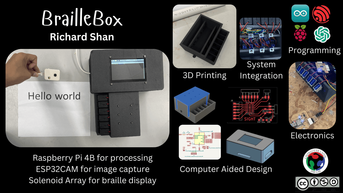
Project poster presentation
Implications & Future Work
There are existing technologies on the market that can convert text to Braille in real time, but those are often expensive and not readily available to the public. My hope with this project is to create a product that can be cheaply produced and reach a wider audience.
Future improvements could include:
- Further miniaturization of components
- More energy-efficient solenoid design
- Integration of multimodal LLMs for scene description beyond just text recognition
- Support for multiple Braille cells to display more characters simultaneously